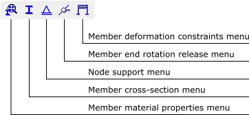
The buttons of this toolbar display a set of sub-menus to create and assign properties for nodes and members of the model. These sub-menus appear along the side of the screen.
The buttons of this toolbar display a set of sub-menus to create and assign properties for nodes and members of the model. These sub-menus appear along the side of the screen.
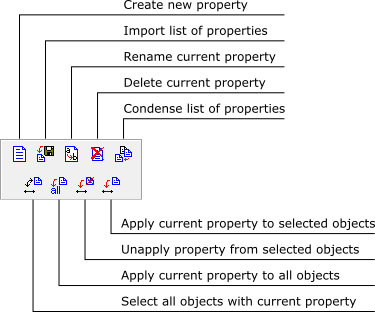
Sub-menus for manipulation of the material parameters, member cross-section properties and values of loads all have common features. The drop-down list (next figure) selects a set of properties that is defined by a unique name. These property values are automatically shown in the sub-menus for editing.
The icons shown in the next figure allow the user to manage these property sets.
To create a new set of properties, select the button
and assign the new set a unique name. The button
imports a list of property sets from another file generated by Ftool. Duplicate property sets in the imported file are ignored. The internal function that compresses the property sets just eliminates those which are not in use in the current model.
To create a new set of material parameters, select button
Material parameters include Young’s modulus (elasticity modulus E), Poisson’s ratio (ν) – used for members with shear deformation, and coefficient of thermal expansion (α) – used in case temperature loadings are applied.
The button

Based on the type of section selected, the parameters that define the features of that section are then defined along the side of the screen under the schematic drawing. There are basically two types of sections: parameterized (including the generic sections) and tabulated.
In the case of parameterized sections, the cross-section’s parameters must be defined. In the case of the Generic section (shown here) the parameters listed are the following geometric properties:
- A: area
- As: effective shear area
- I: moment of inertia (second moment of the area)
- d: section depth
- y̅: centroid position
Each property must be non-zero:
- A: for members with axial deformation
- As: for members with shear deformation
- I: always
- d and y̅: for members with thermal loads
For other parameterized sections, the user defines the section’s dimensions (such as width and height), and its geometric properties are automatically calculated. All dimensions are required but may be equal to zero (so long as the requisite geometric properties are non-zero).
In the case of profile tables, the user need only select the desired profile.
In the case of the section type Profile - Welded-I (BR),
choose the type of profile (Beam, Column or Beam-
Column) and the section depth group, d. Then use the
arrow buttons to choose the desired profile within that
depth group.Ftool contains data from NBR standard profiles, as well as tabulated profiles from different manu-facturers. The user only needs to select specific requirements via the drop-down lists.
Depending on the chosen section type, (all, none or some of) the buttons


will be available. The buttons
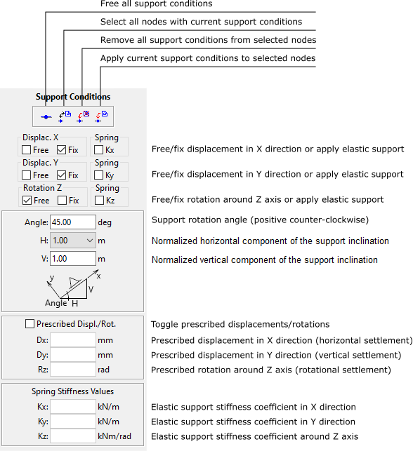
Through this submenu, the user defines constraints on components of displacements in the x and y directions and the rotation around the z-axis. The support orientation angle (for skew supports) is also defined, as well as any prescribed values of displacement or rotation. Prescribed displacements and rotations may only be applied in directions with fixed (rigid) support components. Non-rigid supports may be modeled by specifying values for corresponding stiffness of linear-elastic springs.
Supports are assumed by default to be parallel to the global axes. There are cases, however, when the support is inclined, e.g., when the foundation of a structure rests on a sloped surface rather than on a horizontal surface.
To define an inclined support, its inclination angle from the global axes must be input. A structure node specified as an inclined support will then have local axes (x-y) rotated by the specified angle in relation to the global axes of the structure (X-Y), and the support reactions will be presented with respect to the rotated axes.
For plane (2D) structures, the inclination angle measured from the global X-axis must be input: positive angles in counter-clockwise orientation and negative in clockwise orientation.
In Ftool, the inclination angle may be explicitly specified or computed from a normalized inclination ratio (H/V), in which H is the normalized horizontal component of the inclination and V is the normalized vertical component. The normalized horizontal component may have three possible values: H = 1, H = -1, and H = 0. For H = 1, the local x-axis of the inclined support will be in the same direction as the global X-axis, and the absolute value of the inclination angle will be smaller than 90 degrees. For H = -1, the local x-axis will be in the opposite direction with respect to the global X-axis, and the absolute value of the inclination angle will be greater than 90 degrees. And, for H = 0, the local x-axis will be vertical, upward for V = 1 and downward for V = -1.
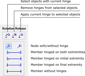
This sub-menu allows the user to introduce hinges at member ends or at the model nodes. By default, members are rigidly connected to the structure nodes.
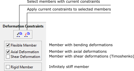
This sub-menu restricts deformations within members. There are two exclusive main options: flexible member and infinitely rigid member. For flexible member, there are two non-exclusive options: toggle for axial deformation and toggle for shear deformation. When a new model is created, the default toggle options are flexible member with axial deformation of with no shear deformation. If a model is read from a file, and all its members have shear deformation allowed, the shear deformation toggle is set on.