Defining the Applied Loads
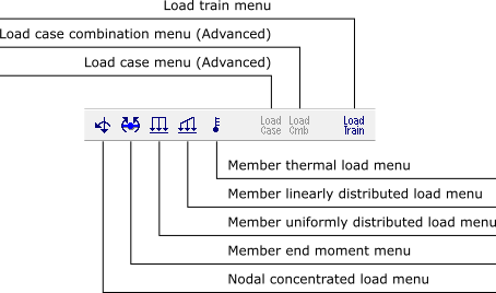
Sub-menus are also available to define or modify various nodal and member
loadings. These sub-menus appear along the side of the screen. The types of
loads available are the following: concentrated loads at nodes, moments
applied at nodes, moments applied at the ends of members, uniformly or
linearly distributed loads along members, variations of temperature applied to
members, and global load-trains (live load for bridges).
The Load case and Load combination menu buttons are only
active in the Advanced Edition (see Advanced
Edition).
-
Load Definition
The loads definition system follows the same procedures as the one that
defines member properties. A type of load associated with a user-supplied
name is created and added to the corresponding load list. The figure below
shows a drop-down list of distributed loads defined by the user in a
specific analysis. The values of load associated with the selected name are
automatically displayed in the fields of submenu and can be edited.

The icons shown in the figure below are used to manipulate the load in a
list:
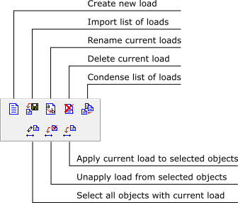
The current load will be applied to the selected elements (members or
nodes). The members of interest must be selected and the load is applied
through the button  for members, or
the button
for members, or
the button  for the nodes.
-
Coordinate System in Ftool
There is a system of structural global axes in Ftool and a system of local
axes for each one of the members. In the global system, the global
X-axis is horizontal and positive from left to right; the global
Y-axis is vertical and positive from the bottom to the top; and the
global Z-axis is always positive outward from the display. In a
member’s local coordinate system, the local x-axis coincides with the
longitudinal axis of the member, with the positive direction following
creation of the member; that is, from the initial node to the end node. The
local x-axis direction can be displayed by selecting the Member
Orientation option in the Display menu (see
Visualization Controls - The Display
Menu). The local y-axis is perpendicular to the
x-axis. The z-axis for a member is always positive outward
from the display. The positive direction of local y then follows the
right-hand rule of vector cross products: y = z × x.
-
Application of concentrated loads
Concentrated loads (forces and moments) can be applied only on nodes of the
structure. Of course concentrated loads could be applied along the span of a
member. However, for user-interface simplicity, it was adopted a police of
only applying concentrated loads at nodes. If it is necessary to apply a
concentrated load on a member, insert a new node at the desired position,
thereby dividing the member into two members. Concentrated loads are always
applied in directions of the global axes of the structure, positive when the
forces have directions of the global axis, and negative when they have the
opposite direction. Positive concentrated moments are applied in a
counter-clockwise orientation.
-
Orientation for distributed member loads
Distributed loads along a member may be specified in the framework of global
coordinates or in the framework of member local coordinates. The loads are
positive if they coincide with the direction of the global or local
axes.
-
Partially distributed member loads
New nodes can be introduced along a member to apply distributed loads that
act on a portion of the member length. As for concentrated loads (see
above), this is done for user-interface simplicity.
-
Load removal from nodes and members
To remove a load from from selected nodes or members, select the first
element (NONE) of the corresponding load drop-down list and apply
this to the selected entities. In other words, "to remove a load from
selected entities in Ftool is to apply nothing".The user may also use
the  button.
This sub-menu allows the user to define the concentrated loads on structure
nodes. It uses the global coordinate system.

This sub-menu allows the user to define concentrated moments at the ends of
members. Moments applied in a counterclockwise orientation are positive.
"Ma" denotes the moment applied at the "initial" node of
the member, while "Mb" is the moment applied at the
"ending" node of the member.

This sub-menu allows the user to define linearly varying or uniformly
distributed loads over a member. The user can specify the global or local
member coordinate system for the loading direction.
This sub-menu allows the user to define a linear temperature gradient over
the member depth. The user specifies the temperature on the section’s top edge
(i.e., on the positive side of local y-axis) and on the bottom edge
(i.e., on negative side of local y-axis). Ftool must have access to the
section depth to impose this loading – even for "generic"
sections.

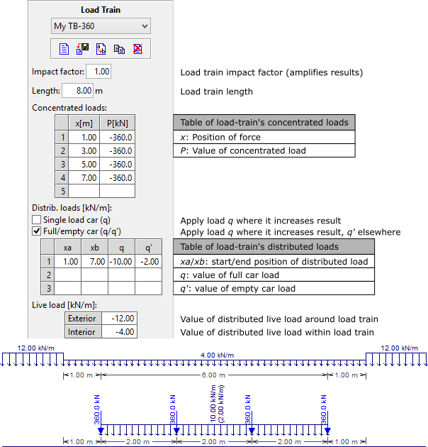
This sub-menu allows the creation of live loads (on bridges, for example)
that are used to calculate envelopes of internal forces (see
Results - Load-train Envelopes Toolbar). A
load-train is composed of concentrated forces, uniformly distributed forces
and live loads (representing the population of small vehicles on a bridge).
Concentrated and distributed loads are assumed in the vertical top-bottom
direction. Therefore, according to the sign convention of Ftool, all load
values are negative. In case the user does not enter a negative sign for a
load value, the program automatically changes the sign of this value.
The concentrated and distributed load matrices resize themselves
automatically: once the user begins to fill out the last row of each matrix, a
new row is created below it. Loads can be deleted by either setting the load
values to zero or by selecting the desired rows and pressing the Delete
key on the keyboard. The matrix will then also resize itself
accordingly.
The currently selected load train may be defined with the dropdown list on
the top-right corner of the program’s window. This dropdown list is only
enabled when in either Influence Line or Load Train Envelope
result modes and/or if in the load train definition menu.
-
Impact factor
This is an amplification factor that multiplies globally all the effects
of a load-train and allows the consideration of a dynamic effect on the
structure. The value of this factor should be always greater than one.
-
Load-train length
This extension length limits the application of concentrated, distributed
and internal live loads.
-
Concentrated forces
Load-train concentrated forces are specified using a matrix with two
columns, with the following parameters:
- x - position of concentrated force in relation to load-train
beginning;
- P - value of a concentrated force.
It is not allowed to create more than one concentrated force at a
single position, or outside the limits of the load train (specified by its
length). To add a concentrated force to the current load-train, first
enter the force position then its value. As other concentrated forces are
inserted, they are ordered according to their position.
-
Uniformly distributed forces
The matrix of distributed forces varies according to the type of
load-train. In case of a load-train that has single values of distributed
forces, the matrix has three columns for the following parameters:
- xa - initial distributed force position in relation to
load-train beginning;
- xb - end distributed force position in relation to load-train
beginning;
- q - value of a distributed force.
In case of a load-train that has full and empty cars, q becomes
the value of the distributed force for a full car and the matrix has an
additional column for the following parameter:
- q’ - value of a distributed force for na empty car in a
railroad load-train.
Overlap of distributed forces is not allowed. Initial and end positions
of distributed forces must be within the load-train extension (length). To
add a distributed force to the load-train, first enter its initial and end
positions then the load value(s). In the case of a railroad load-train,
the first load value to be inserted is q and then q’.
As other distributed forces are inserted, they are ordered according to
their initial and end positions. When xa is greater than xb,
or q is less than q’, these values are automatically
inverted. It is possible to modify the type of load-train, even after
distributed forces have been inserted. When transforming a load-train with
single value distributed force to a load-train with double distributed
load value, q’ is set equal to q.
-
Live loads
There are two types of live loads that represent the population of small
vehicles on a bridge:
- Exterior: is applied outside the limits (length) of current
load-train;
- Interior: is applied within the limits (length) of current
load-train.
Live loads may be applied partially along the load-train path on the
structure. The portions of the path on which live loads are applied depend
on influence lines. These portions are defined to maximize or to minimize
a target effect. The maximum value of an effect is obtained applying the
live load only on the positive portions of the influence line of that
effect; and the minimum value is obtained applying the live load only on
the negative portions of the influence line.

